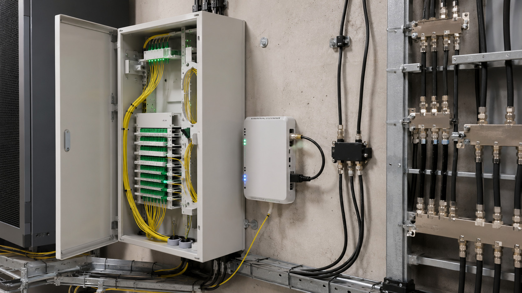
RF over Glass extends familiar CATV and DOCSIS services across passive fiber infrastructure. It enables operators to move fiber closer to subscribers while preserving established headend systems and customer equipment. Successful deployment depends on accurate optical budgeting, controlled upstream transmission, clean fiber installation, appropriate RF levels, and comprehensive performance testing. When these requirements are met, RFoG offers a reliable bridge between traditional cable networks and the next generation of fiber-based access.
RF over Glass (RFoG) is a fiber-access technology designed to transport traditional cable television and broadband signals over optical fiber. It allows network operators to replace long coaxial sections with fiber while retaining existing DOCSIS platforms, cable modems, set-top boxes, and headend equipment.
By combining passive optical distribution with established cable-network technology, RFoG provides a practical migration path toward fiber-rich access infrastructure without requiring an immediate transition to a fully digital passive optical network.
What Is RF over Glass?
RFoG carries downstream and upstream radio-frequency signals through optical fiber. At the headend or hub, the downstream CATV signal is converted into an optical signal and distributed through a passive optical network. At the subscriber location, an RFoG optical network unit converts it back to an electrical RF signal for delivery over a short coaxial connection.
The return path works in the opposite direction. Signals generated by a cable modem or other interactive device are received by the RFoG unit, converted into an upstream optical transmission, and sent back toward the operator’s network.
From the perspective of subscriber equipment, the connection behaves much like a conventional hybrid fiber-coaxial network. The main difference is that fiber reaches much closer to-or directly into-the customer premises.
Main System Components
A typical RFoG network contains:
- Downstream optical transmitters at the headend or optical hub.
- Optical amplifiers where additional reach or splitting capacity is required.
- Passive optical splitters that distribute signals to multiple subscribers.
- Single-mode fiber connecting the hub with customer locations.
- RFoG optical network units at subscriber premises.
- Short coaxial connections to televisions, set-top boxes, and cable modems.
- Optical return-path receivers at the headend.
The passive outside plant requires no powered amplifiers between the optical source and subscriber units. This can reduce field maintenance and eliminate many problems associated with active coaxial distribution equipment.
Downstream Signal Distribution
In the downstream direction, the complete RF spectrum is used to modulate an optical carrier. This spectrum may contain digital QAM television channels, DOCSIS downstream carriers, and other compatible RF services.
The optical signal passes through fiber and passive splitters before reaching each RFoG unit. The unit converts the optical input into an RF output, which is then distributed to subscriber devices.
Because every device receives the same RF channel lineup, the operator can continue using familiar service provisioning and conditional-access systems. Existing cable modems and televisions generally do not need to understand that fiber is being used for most of the access path.
Upstream Transmission
Return-path operation is more challenging because multiple RFoG units share the same upstream optical receiver. Each unit activates its return transmitter when it detects a signal from connected subscriber equipment.
Only devices with upstream traffic should transmit at a given moment. However, when two or more units activate simultaneously, their optical signals can overlap at the receiver. This condition is known as optical beat interference.
Optical beat interference may degrade the upstream signal and cause packet loss or reduced modem performance. Modern RFoG systems can address the problem using controlled return-path transmission, coordinated optical units, wavelength-management techniques, or specialized receivers.
Upstream design must therefore account for the number of connected units, optical power levels, splitter loss, transmitter behavior, and expected DOCSIS traffic.
Optical Power Budget
A reliable RFoG deployment requires a carefully calculated optical power budget. The budget should include:
- Fiber attenuation.
- Connector and splice losses.
- Passive splitter insertion loss.
- Engineering and aging margins.
- Transmitter output power.
- Optical amplifier gain and noise.
- Minimum and maximum receiver input levels.
Too little optical power can reduce carrier quality and cause service interruptions. Excessive power may overload optical receivers. Both conditions can affect digital modulation performance even when an RF signal is still visible at the output.
Engineers should verify the design with calibrated optical power meters and evaluate RF performance after optical conversion.
Benefits of RFoG
RFoG offers several operational advantages:
- Fiber can reach individual buildings, apartments, or homes.
- Existing DOCSIS and CATV equipment can remain in service.
- Passive optical distribution reduces powered field electronics.
- Fiber provides low attenuation over long distances.
- The network is resistant to electromagnetic interference.
- Available bandwidth is less constrained by long coaxial cascades.
- The fiber infrastructure can support future migration to PON technologies.
These benefits make RFoG useful for greenfield residential projects, multi-dwelling units, hospitality properties, campuses, and areas where maintaining a conventional coaxial plant would be difficult or expensive.
RFoG and PON Coexistence
One important feature of RFoG is its ability to coexist with certain passive optical network services over the same fiber infrastructure. Separate optical wavelengths can be used for RF video and data services, provided that the transmitters, receivers, filters, and splitters are designed for the selected wavelength plan.
This allows operators to deploy RFoG as an intermediate stage and later introduce GPON, XGS-PON, or another access technology. The passive fiber plant may remain in place while customer equipment and central-office platforms are upgraded gradually.
Careful wavelength planning is essential to prevent interference and ensure that every component supports the intended optical bands.
Installation and Testing
RFoG networks require both optical and RF testing. Technicians should inspect and clean fiber connectors before connection, measure optical power at strategic points, and confirm that splitter losses match the design.
At the RF output of each optical network unit, testing should include signal level, modulation error ratio, bit error rate, and upstream modem performance. Technicians should also check coaxial cables, splitters, terminations, bonding, and shielding within the premises.
Network monitoring should track optical levels, upstream noise, modem connectivity, and error rates. Changes in these values can reveal damaged fiber, contaminated connectors, excessive reflections, or return-path interference.